-
teléfono : +86-592-6382791
-
Email : sales@pidmaxwell.com
teléfono : +86-592-6382791
Email : sales@pidmaxwell.com


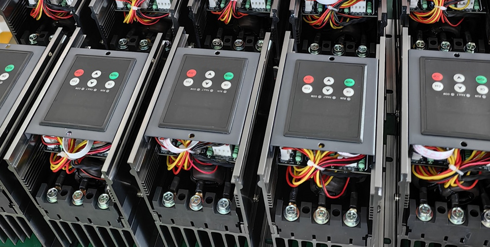
Los reguladores de potencia (también conocidos como unidades de control de potencia) son actuadores clave en el control de calentamiento eléctrico industrial, y su función principal es regular la potencia de salida. Sin embargo, muchos usuarios pasan fácilmente por alto el hecho de que los reguladores de potencia ofrecen más de un método de regulación de potencia. Diferentes cargas de calentamiento tienen características eléctricas variables y diversos requisitos de proceso, lo que requiere distintos métodos de control. Los métodos comunes de regulación de potencia en el mercado se dividen principalmente en cuatro categorías: control de fase (control por desplazamiento de fase), control por cruce por cero (control de posición cero/control de ciclos), control de regulación de tensión y control de regulación de potencia. Comprender estos principios básicos ayudará a evitar errores en la selección de potencia.
¿Por qué el método de regulación de potencia afecta la selección de potencia? El papel de un regulador de potencia es controlar con precisión la potencia de salida, pero diferentes cargas tienen requisitos muy distintos para el método de salida. Los elementos calefactores comunes y los cables resistivos tienen una resistencia relativamente estable durante el funcionamiento, lo que facilita su control; sin embargo, las lámparas infrarrojas, las varillas de carburo de silicio, las varillas de molibdeno y silicio, y las cargas de transformador tienen características eléctricas mucho más complejas. Por ejemplo, las varillas de carburo de silicio tienen una región de resistencia negativa en el rango de 700-800℃: la resistencia disminuye a medida que aumenta la temperatura. Si el método de control no es adecuado, puede producirse fácilmente una fuga descontrolada de corriente. Las cargas inductivas de tipo transformador son muy sensibles al componente de corriente continua en la forma de onda de salida. Un sesgo excesivo de corriente continua puede provocar la saturación del transformador o incluso su quemado. Si el método de regulación de potencia no coincide con las características de la carga, pueden producirse problemas como un control de temperatura inestable,salida anormal, interferencia armónica excesiva y efectos de calentamiento insatisfactorios. El verdadero núcleo de la selección de carga no reside en la potencia nominal, sino en la compatibilidad entre las características de la carga y el método de regulación de potencia.
El control por cruce por cero (regulación de potencia por cruce por cero) activa o desactiva un tiristor cuando la tensión de CA se aproxima a cero, cambiando la proporción de salida en unidades de ciclos completos de onda sinusoidal. Las ventajas principales de este método son una forma de onda de salida completa y sin distorsión, y una contaminación armónica mínima para la red eléctrica. Debido a que la conmutación ocurre en el punto de cruce por cero, las pérdidas de conmutación y la interferencia electromagnética también son relativamente bajas. Es adecuado para cargas de calentamiento resistivas comunes, como elementos calefactores, cables resistivos, hornos, hornos eléctricos y equipos de calentamiento por aire caliente. Para aplicaciones con alta inercia térmica y donde se permite cierta fluctuación de potencia, el control por cruce por cero es una opción económica.
El control de fase (control por desplazamiento de fase) ajusta la salida cambiando el ángulo de conducción de los tiristores en cada semiciclo de la corriente alterna. Un ángulo de conducción mayor produce una potencia de salida más alta, mientras que un ángulo menor produce una potencia de salida más baja. Este método logra una regulación de potencia continua y uniforme con alta precisión de control, pero a costa de recortar parcialmente la forma de onda de salida, generando armónicos y contaminando la red eléctrica. Es adecuado para aplicaciones que requieren variaciones de potencia más precisas y ajustes continuos, pero debe evaluarse la tolerancia del entorno eléctrico del sitio frente a los armónicos.
El control de regulación de tensión se centra más en cambiar la magnitud de la tensión de salida, afectando indirectamente la potencia de calentamiento. En aplicaciones prácticas, el control de regulación de tensión suele estar estrechamente relacionado con la tecnología de control de fase. Algunas cargas especiales son sensibles a los cambios de tensión y pueden requerir métodos especializados de regulación de tensión. Por ejemplo, en sistemas de calentamiento con transformadores, la regulación de tensión puede minimizar las sobrecorrientes de la carga. Al seleccionar el control de regulación de tensión, no se puede aplicar simplemente la experiencia de selección de elementos calefactores eléctricos comunes; es necesaria una evaluación cuidadosa de si la carga es adecuada para una regulación continua de tensión.
El control de regulación de potencia enfatiza el ajuste proporcional de la potencia media. No necesariamente cambia cada forma de onda de manera continua, sino que modifica la potencia media recibida por la carga controlando la proporción de estados de encendido y apagado durante un período de tiempo. El control por cruce por cero es una implementación típica del control de regulación de potencia. Además, el control de regulación de potencia puede dividirse en dos modos: regulación de potencia de ciclo constante y regulación de potencia de ciclo variable. La regulación de potencia de ciclo variable (también conocida como regulación de potencia por ciclos) puede acortar el ciclo de control tanto como sea posible mientras cumple los requisitos de activación por cruce por cero, distribuyendo uniformemente la forma de onda de salida y evitando el impacto de ciclos concentrados de encendido/apagado en la red eléctrica. Para la mayoría de los equipos de calentamiento resistivos, el control de regulación de potencia ya puede cumplir los requisitos de control estable de temperatura.
Entonces, ¿cómo elegir entre los diferentes métodos de regulación de potencia? No existe una fórmula universal. Los principios básicos son: primero, considerar el tipo de carga; segundo, considerar los requisitos de control. Para tubos calefactores comunes y cables resistivos, generalmente se prefiere el control por cruce por cero (método de regulación de potencia) debido a su alta rentabilidad y baja interferencia. Para aplicaciones que requieren cambios de salida más continuos, puede considerarse el control de fase según las condiciones reales de funcionamiento. Para cargas con varillas de carburo de silicio, debe prestarse atención a sus características de resistencia negativa a 700-800℃. Se recomienda seleccionar la capacidad de corriente del regulador de potencia al menos 1,3 veces la corriente de carga. Si no se utiliza un transformador, las varillas de carburo de silicio deben conectarse en serie para aumentar la impedancia. Las cargas como varillas de molibdeno y silicio, alambres de molibdeno y tungsteno presentan grandes variaciones de resistencia entre estados caliente y frío, perosu resistencia está relacionada linealmente con la temperatura. Se recomienda activar la función de arranque suave al encender (ajustable de 1 a 120 segundos) para reducir eficazmente el impacto inicial. Las cargas de transformador son cargas inductivas, por lo que requieren especial atención al control del componente de corriente continua en la forma de onda de salida para evitar la saturación magnética del transformador. Se recomienda seleccionar un regulador de potencia con función de arranque suave y modo de activación por cruce por cero. Ningún método individual es adecuado para todos los equipos; la clave es considerar la aplicación específica.
Elegir un método incorrecto de regulación de potencia puede provocar una serie de consecuencias adversas: grandes fluctuaciones de temperatura y control de temperatura inestable; la incompatibilidad entre el método de control y la inercia térmica de la carga provoca oscilaciones repetidas de temperatura; calentamiento lento y baja eficiencia térmica; el método de salida de potencia no es adecuado para las características de la carga, lo que provoca una salida de calor insuficiente; aumento de la interferencia eléctrica; los armónicos generados por el control de fase pueden interferir con otros equipos de precisión conectados a la misma red eléctrica; reducción de la vida útil de los elementos calefactores; por ejemplo, si una varilla de carburo de silicio pierde el control en la región de resistencia negativa, un aumento repentino de corriente puede quemar directamente el elemento; incluso daños en los equipos; sobrecorriente, sobrecalentamiento o incluso quemado del módulo de tiristor dentro del regulador de potencia; y un sesgo grave de corriente continua en cargas de transformador puede provocar daños por saturación del transformador. Las cargas que requieren regulación continua de tensión puedenno lograr el efecto de calentamiento deseado si se utiliza un método de control inadecuado; y los métodos de control seleccionados incorrectamente para cargas resistivas comunes también pueden aumentar interferencias armónicas innecesarias.
Además del método de regulación de potencia, el proceso de selección también requiere una consideración exhaustiva de factores como el tipo de alimentación eléctrica, la corriente nominal y la potencia de carga, el tipo de señal de control, el entorno de instalación y las condiciones de disipación de calor. El tipo de alimentación eléctrica debe distinguirse entre monofásica y trifásica. Para potencias medias a altas (por encima de decenas de kilovatios), generalmente se recomienda un regulador de potencia trifásico, ya que puede equilibrar eficazmente la carga de la red eléctrica. La corriente nominal debe tener un margen de 1,3 a 1,5 veces la corriente de carga real; para cargas especiales como las varillas de carburo de silicio, se necesita un margen mayor. La señal de control debe confirmarse para que coincida con la señal del controlador de temperatura o del sistema PLC. En cuanto al entorno de instalación, el regulador de potencia generará calor durante el funcionamiento prolongado, por lo que debe instalarse verticalmente con suficiente espacio para la disipación de calor en ambos lados. El gabinete de control debe tener orificios de ventilación por convección de aire, y se recomienda la refrigeración por aire forzada para corrientes de funcionamiento superiores a 30 A. La disipación de calor es crucial;una mala disipación de calor hará que la temperatura interna del regulador de potencia aumente continuamente, lo que puede provocar alarmas de sobrecalentamiento o incluso el envejecimiento y daño del módulo, aunque el método de regulación de potencia se haya seleccionado correctamente.
En resumen, los reguladores de potencia tienen cuatro métodos principales de regulación de potencia: control por cruce por cero, control de fase, control de regulación de tensión y control de regulación de potencia. La clave de la selección no es la potencia nominal, sino la correspondencia entre las características de la carga y el método de regulación de potencia. Definir claramente primero el tipo de carga y los requisitos de control garantizará un funcionamiento más estable y una vida útil más larga para los equipos de calefacción.

dirección : NO.201 Binhuyili, HaiCang district, XiaMen,FuJian, China 361026
Max liao: +8618150368619(whatsapp)
Email : sales@pidmaxwell.com
escanear a través de wechat

Scan to Whatsapp